
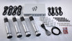
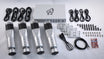


Hardware Installation
Your new DK motion system is designed to be mounted on t-slotted aluminum extrusions. The included bracket is designed to fit a variety of aluminum extrusion including, 10 and 15-series (inch) or 40 and 45-series (metric) profiles.
Step 1: Pre-Install the DK Motion Bracket to each Actuator
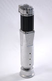
Using a 5mm hex key, attach the mounting bracket to the actuator with the included M8
screws. You may wish to apply some of the included medium strength Loctite thread
locker to these screws. Torque to 180 in-lb. (15 ft-lb, 20.3 N-m).
Step 2: Place the T-Nuts in the Extrusion
Install the provided t-slot nuts into your profile. The t-nuts can be installed by sliding them into the side of the profile (easiest) or by angling them directly into the profile from the face side and the using a thin tool to position them into place. 
* TIP - You might also be able to preassemble the bracket with the t-slot nuts and slide the actuator onto the chassis extrusion. See our instructional video here: DK Motion Actuator Install
Step 3: Mount the Actuator with Bracket to the Extrusion
With your chassis supported, align the holes in the mounting bracket with the four t-slot
nuts. Attach the bracket and actuator to your chassis with the included M8 screws using
a 5mm hex key. You may wish to apply some of the included medium strength thread
locker to these screws. Torque to 180 in-lb. (15 ft-lb, 20.3 N-m).

Step 4: Actuator Install Location
For a 3-actuator systems, install the single actuator at the front and the two actuators at the back. It is recommended to place the two actuators at the back to support the heaviest part of the rig, the driver.

For 4-actuator systems, it is recommended to position the rear actuators at the very back of the simulator, then position the front actuators as far back as possible without upsetting the balance of the simulator. This ensures the best possible weight distribution and performance.

With a tape measure, record the Length and Width (center-to-center) distances as indicated above. These measurements are to be entered in the Sigma software to ensure that proper pitch and roll are mechanically represented and calculated by our algorithms.
* TIP - Try to square off the driver with the actuators as much as possible. This will give you the most amount of mechanical pitch and roll. See our instructional video here: DK Motion Actuator Placement
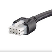
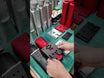
Step 5: Connect the Cables from the Motor to the Controller
Connect the power (4-pin cable) and signal cables (8-pin cable) to each of the motors. Route the cables so they are strain relieved, and are clear from possible pinch hazards.

Connect the cables to the DK controller as shown below:

Place the DK controller on the floor or mount the controller securely to the rig using the provided tabs and your choice of fasteners. Each rig is different and so if you are unable to mount the controller to the rig, you may want to just leave it placed underneath the rig on the floor.
The system specifically comes with two sets of 1 meter and 2 meter cables so that the controller may be places in the back or the front of the rig without excess cable lengths. Extended cables are available for an additional charge.
* TIP - You can rotate your DK actuators if there is any interference. Please see this instructional video here: DK Motion System Motor Orientation
* Customers who wish to relocate the power switch to their chassis can use one of these standard remote power switches or a wireless power switch.
Step 7: Connect the Controller to the Computer
Connect the included power and ethernet cables from the controller box to your PC’s network port. If a network port is not available, you may purchase a USB to Ethernet adapter. Sigma does not provide a USB to network adapter as they are abundant an we do not want to supply unnecessary hardware that might never be used in your unique setup. Almost any standard USB to Network adapter will do.
* TIP - Quick Overview of the Sigma DK Motion Controller (VIDEO)
Step 8: Power up the DK System
When ready, plug the power cable into the wall electrical outlet.
Ensure the AC voltage supply matches the DK controller (95-125VAC, 190-250VAC).
If everything is properly installed, the controller will turn on with all the lights on and the actuators will have an amber (yellow) light at the top of the all the motors.
Please continue the rest of the software installation here: SOFTWARE INSTALLATION.